PoradnikAuthor: Patrycja Marciniak
Filigree slab — spans, thicknesses, reinforcement

A filigree slab is a composite slab: on site the thin precast unit acts as permanent formwork, and the structure reaches its full capacity only once the structural topping has been cast. This article gathers the parameters design starts from — spans, thicknesses and reinforcement quantities — together with the limits beyond which the solution stops making sense.
What a filigree slab consists of
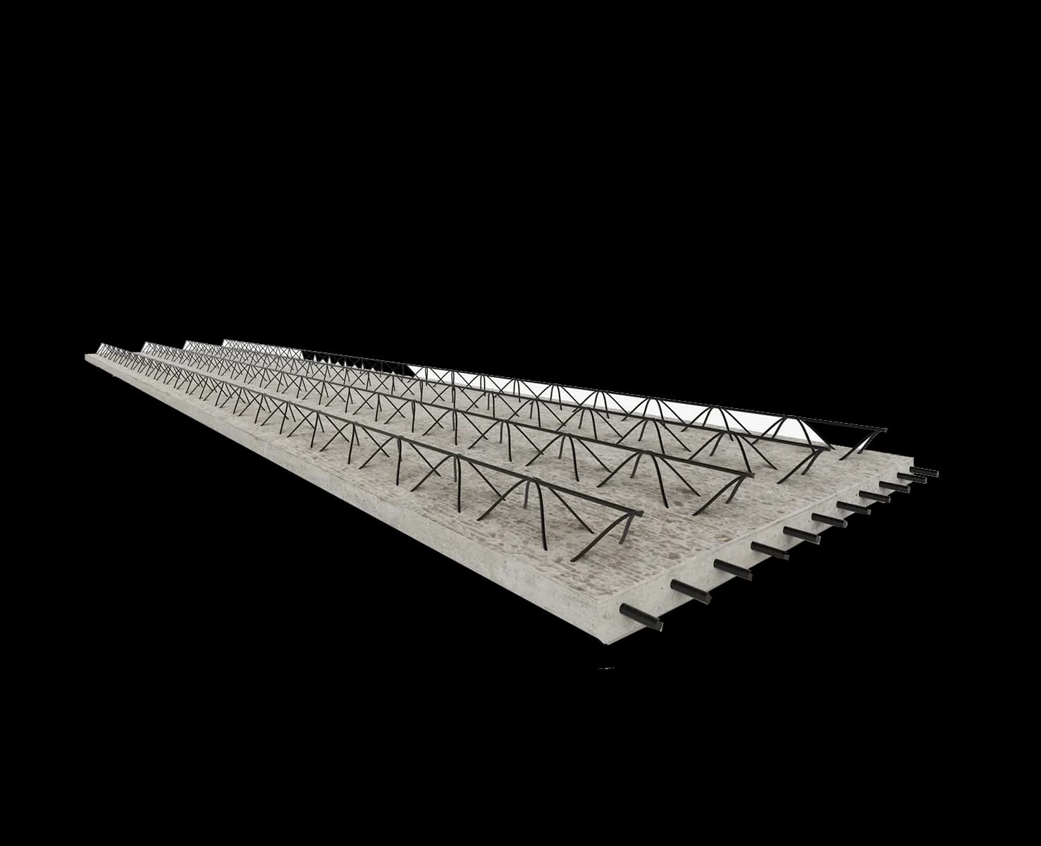
The precast unit is more than 5 cm thick and at that thickness weighs about 125 kg/m². Lattice girders project from its upper face; during erection they stiffen the plank, and once the topping is cast they bond the precast unit and the topping into a single composite section.
The total depth of the finished slab falls between 14 and 40 cm. The difference between that figure and the thickness of the precast unit is the structural topping placed on site, together with top reinforcement, ring beams and trimming around openings.
The underside of the plank leaves the mould smooth, ready for a thin-coat plaster or wallpaper. That surface becomes the ceiling — with no levelling render and no suspended ceiling, unless the design calls for one.
| Parameter | Value |
|---|---|
| Unit width | ≤ 2.50 m |
| Plank length | < 12 m |
| Precast unit thickness | > 5 cm |
| Total slab depth | 14–40 cm |
| Weight at 5 cm thickness | approx. 125 kg/m² |
| Concrete class | up to C35/45 |
| Bearing on the wall | 20 mm |
Which span to assume
The technical catalogue sets out slab spans from 2 to 8 metres, at imposed loads from 1 to 9 kN/m². That is the practical range in which filigree slabs work in residential, office and industrial construction.
Spans are not, however, taken from a table in isolation from the rest of the design. They are governed simultaneously by the imposed load, the total slab depth, the arrangement of permanent supports and the permissible deflections. Every slab is drawn and calculated individually in our design office, in line with the building's specification and structural requirements.
A unit width capped at 2.50 m and a length below 12 m are transport and production limits — larger areas are divided into several planks, with connecting reinforcement provided at the joints between them.
How much reinforcement — indicative figures
The reinforcement selection table on the filigree slab product page allows steel requirements to be estimated before the detailed design exists. Columns correspond to the span in metres, rows to the imposed load in kN/m², and each cell gives two values: the total estimated mass of reinforcement and the part of it already contained in the precast unit.
For the most common residential situations — spans of 4.5 to 6 m at loads of 2–3 kN/m² — the total estimated reinforcement mass falls between 18 and 22, of which 6–7 belongs to the precast plank itself. The remainder is reinforcement placed on site before concreting.
These are indicative values, intended for a preliminary estimate of materials. Detailed reinforcement design requires full structural calculations in accordance with the applicable standards.
Lattice girders and additional reinforcement
The lattice girders serve three purposes at once: they stiffen the thin precast unit for transport and erection, they provide the attachment points for lifting slings, and they ensure composite action between the precast unit and the topping.
Beyond the factory reinforcement, work on site covers reinforcement at the joints between planks, additional bottom reinforcement, top reinforcement, ring beams, downstand beams and trimming around openings and penetrations — all in accordance with the drawings for the specific building.
A mesh in the joint is not required where the joints between precast units are reinforced with additional bottom reinforcement.
What is not permitted: cutting the lattice girders or the reinforcement of the precast unit without the written approval of the designer. Openings not shown in the design require their position relative to the reinforcement to be checked, regardless of diameter — including small ones.
Services within the slab
Lighting points, loudspeakers, ventilation and cable outlets can be integrated into the plank at the plant, together with empty conduits. Inserts and service components are recorded in the technical planning as drawings and, where necessary, allowed for structurally.
A clash-detection system identifies conflicts between disciplines before production rather than on the building site. Computer-controlled placing of service components in the mould ensures accurate positioning.
In practice this means one thing: the earlier services enter the model, the fewer chases and drilled penetrations after concreting — and chases may only be cut in the zones permitted by the documentation.
When a filigree slab is the wrong choice
Honestly about the limits of the solution:
- Where there is no crane access. The planks arrive finished and have to be lifted into place. A tight plot with no room to manoeuvre rules the technology out before anything else is calculated.
- Where props cannot be set up. Until the topping gains strength the slab works on props. This is not an immediately loadbearing solution in the way a hollow-core slab is.
- On complex floor plans with many small, irregular bays. The advantage of precast grows with repetition; a fragmented plan consumes it by splitting the floor into many one-off planks.
- Where the programme has no allowance for wet work. The topping is concrete placed on site, with a full curing cycle.
In every other situation a filigree slab delivers what an in-situ slab cannot: a finished ceiling from below, no formwork, and a predictable time for the floor. We have set the two solutions side by side in filigree or in-situ slab, and the erection sequence itself in the step-by-step installation guide.
Full technical data, the reinforcement selection table and detail drawings are on the filigree slab product page. If you have a floor plan and a section, send them for a quotation — the division into planks is settled at the shop-drawing stage.