Guides
BIM in precast: how we work in Tekla Structures
At Formee every project, without exception, is built as a structural model in Tekla Structures, and the shop drawings, reinforcement schedules, embedded item lists and erection drawings are generated from that model. We do not require a model from the designer: dimensioned plans, sections and elevations in PDF or DWG are enough for a quotation, and an IFC file only shortens the work. Clashes with building services are resolved in the model before anything goes into production.
The word BIM appears in every construction offer these days, so we pin it down: we have no drawings drafted separately and no schedules calculated by hand. This text sets out what that changes for the designer and for the investor.
One model instead of a set of drawings
In traditional construction the documentation is a collection of drawings that somebody has to keep consistent with one another. In precast such a collection is not enough, because every element has its own geometry, its own reinforcement, its own cast-in items and its own number. With several hundred elements in a multi-family building, keeping that consistent by hand ends in an error.
So we work the other way round: first the model, and only then the documents. From the model in Tekla Structures we generate shop drawings for every element, reinforcement schedules, cast-in item lists, weights and lifting points, along with the data that gives production and loading their sequence. A change in the model carries through to all of those documents at once, so the element drawing and the reinforcement schedule cannot drift apart.
What we need from the designer
We do not require a model. For pricing, dimensioned plans, sections and elevations are enough; for shop drawings we need the architectural and structural documentation, in PDF or DWG. If the designer works in BIM and can hand over a model in IFC format, it shortens our work and reduces the risk of error when transferring geometry — but it is not a condition.
Splitting the structure into elements is our job, and we agree it together with the designer. It is decided not only by the structural analysis, but also by transport dimensions, the crane capacity available on the particular site and how many identical elements can be drawn from one mould. This is the stage at which most of the cost is settled, so the earlier the documentation reaches us, the more room is left for optimisation.
The second thing we need before production is the services routing. Electrical boxes, conduits, penetrations and openings for ventilation ducts are set in the mould, so they have to be resolved in the shop drawings. Chasing a reinforced concrete wall after the fact is possible, but it costs money and risks hitting the reinforcement — the model exists precisely to avoid that.
Clashes show up on screen
We combine the structural model with the services routing and check for clashes before anything goes into production. A drainage pipe running through a beam, a ventilation duct where a column stands, a box on the line of the reinforcement: in traditional construction these appear on site, after the concrete has been poured, and end in breaking out or rerouting the services. In the model they appear on screen and end with an opening moved a few centimetres.
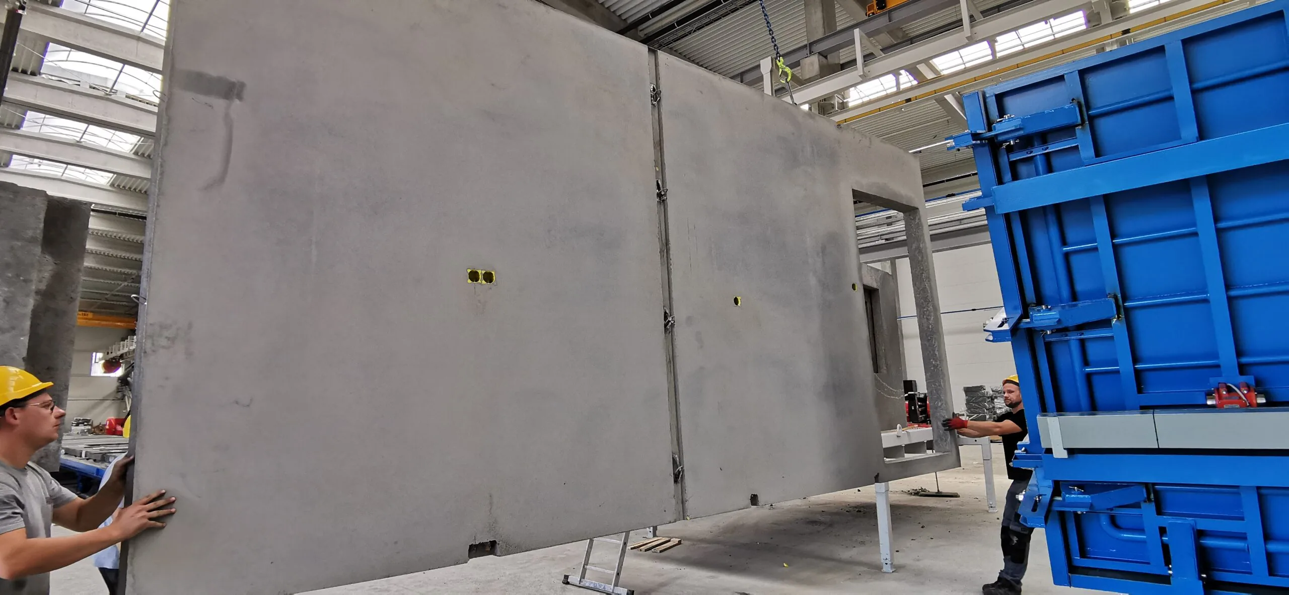
On site this means the services contractor receives a wall with openings and boxes exactly where they were designed, and not where the bricklayer found it convenient to put them.
A change in the model and a change after casting
Precast is sometimes called a rigid technology. It is worth saying honestly where that rigidity really lies and where there is none at all.
Until the shop drawings are approved, a change is an edit to the model: moving a window, adding a box, a different spacing of openings regenerates the drawings and schedules automatically. Here precast is more flexible than traditional construction, because the consequences of a change are visible at once on every element it affects.
The rigidity starts the moment an element is cast. A change after that means a new element, not a correction on site. The whole process is therefore arranged so that decisions are taken earlier: approval of the shop drawings is the point at which we start production, and we say so at the beginning rather than at the first change.
From the model to the mould and to site
Element data from the model feeds production planning: the reinforcement sequence, the setting out of moulds, cast-in items, the casting date and the dispatch date all follow from the same list that fixes the erection sequence. The automated reinforcement line in the plant receives mesh geometry straight from the documentation, without anyone retyping dimensions.
That same list then governs the loading of the trailers in reverse erection order, so that an element comes off the transport straight into its position. What that part looks like is described in a separate text on delivery logistics.
On site the erection crew works from erection drawings generated from the same model, with the number of every element and its position. Dimensional deviations at acceptance are assessed against EN 13369, EN 13670 and ISO 7976; the acceptance documents are collected under compliance and certificates.
What the investor gets out of it
Three things that can be checked. First, the documentation is consistent because it has a single source, so acceptance of the elements and of the erection is carried out against the same drawings that production worked from. Second, services clashes were resolved before production, so there is no breaking-out and patching stage on site. Third, the full set of element drawings and schedules is ready for the as-built documentation, without reconstructing anything after the fact.
What the whole process from documentation to handover looks like is described on the services page. We prepare a quotation on the basis of dimensioned plans and sections, usually in about a week — ask for a quotation.